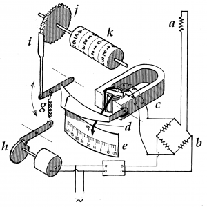
I’m indebted to Dr Peter Harris for unearthing this curiosity, published in the journal of the Institute of Heating and Ventilating Engineers in 1936. It is a design for a “degree-day meter” whose purpose was to summarise how cold the weather had been over a given period (a month, say). This is how it works: a resistance thermometer a is mounted outdoors and connected via a Wheatstone Bridge b to a moving coil galvanometer c whose pointer d moves horizontally across a scale e, marked from 60°F on the left to -20°F on the right. It thereby indicates the outside air temperature. Above the pointer is a tapered chopper bar f, moved up and down by a light spring g driven by a rotating cam h. Because the chopper bar is tapered, its vertical travel is constrained to an increasing extent as the pointer moves leftward indicating higher temperatures. Conversely, its vertical travel will be greater the lower the temperature, as the pointer moves to the right. The intermittent vertical travel of the chopper bar is transmitted via a pawl i and ratchet-wheel j to a cyclometer counter k which shows the total vertical travel. The counter will advance more rapidly when it is colder and more slowly when it is warmer outside, and it is so arranged that when the temperature exceeds 60°F there will be no vertical play and the counter will not advance at all.
Because a building’s heating power requirement at any given moment is proportional to the temperature deficit, the accumulated deficit over any given period of days (as measured by this meter) is proportional to the total thermal energy lost from the building, which needs to be made up by the heating system. Because it measures the time integral of temperature deficit, its units of measurement are degree-days (analogous to man-hours) and the threshold temperature of 60°F survives today as the common degree-day base temperature of 15.5°C.
